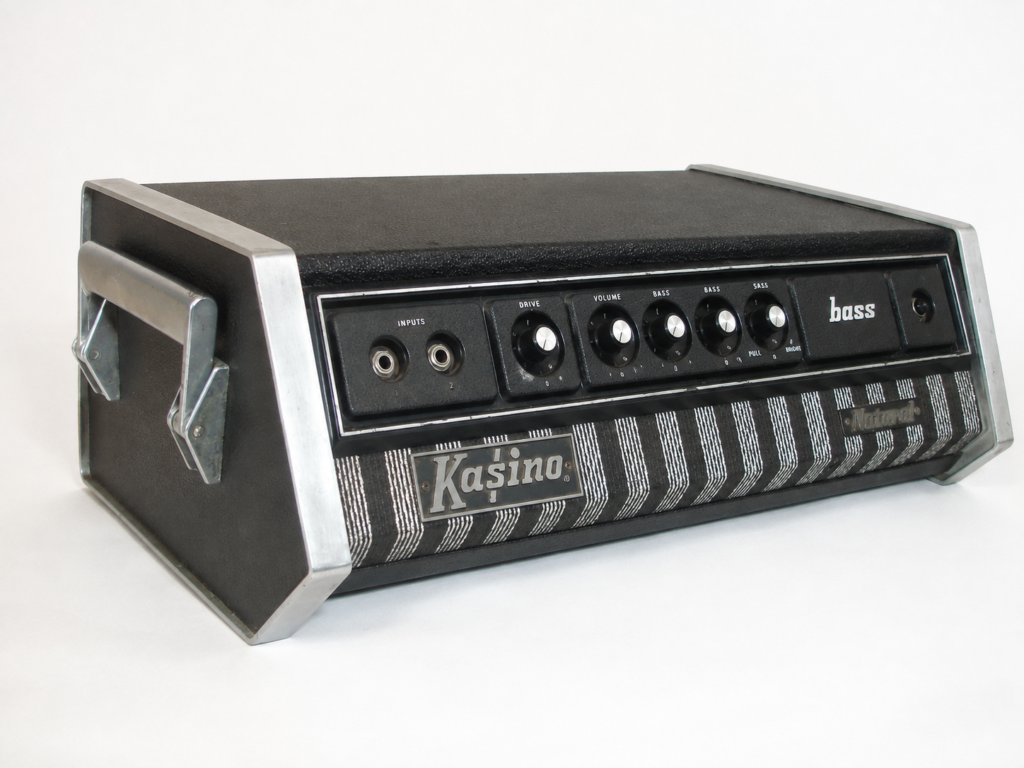
Project Scope: Vintage solid-state audio repair, schematic signal tracing, and capacitor replacement bench log.
⚠️ SAFETY WARNING: High-Voltage Capacitors Audio amplifiers store dangerous DC voltages in power supply filter capacitors even when disconnected from AC mains power. Always safely discharge power supply capacitors before touching internal components.
Technical Specifications: 1970s Kasino Natural Bass Amp
| Specification | Details |
| Manufacturer | Kustom Electronics (Kasino Brand) |
| Model | Kasino Natural Bass Amp |
| Era | Early 1970s |
| Topology | Solid-State |
| Output Power | 75 W RMS / 150 W Peak |
| Board Schematics | 5104 Preamp Board / 5033 Power Amp Board |
Background & History: Kustom vs. Kasino
In this installment of “The Repair Bench,” we are repairing a vintage Kasino Natural model bass amplifier head from the early 1970s.
The Kasino brand was made by Kustom Electronics, maker of Kustom Amplifiers. If you’re not familiar with them, the Kustom amps brand was famous for covering their amplifiers in “tuck and roll” style upholstery (Photo 1), previously used in hot rod cars interiors.
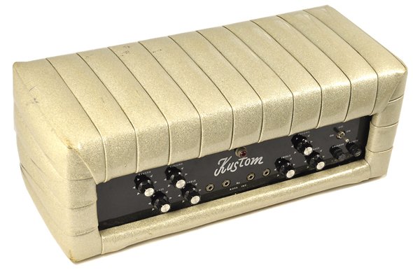
Photo 1 – Vintage Kustom tuck and roll naugahyde upholstery
While these amps were famous for their unique look, they also had a large following among notable artists for their great sound. Kustom was a leader in high-end, solid-state amplifier design, and famous artists using their equipment at the time included Creedence Clearwater Revival, Johnny Cash, Carl Perkins, and Waylon Jennings.
Their position as a high-quality amplifier, with fancy upholstery, made their product expensive and limited the market size. To expand their dealer network and sell a less expensive product, Kustom created the Kasino amplifiers brand, using the same designs but with traditional Tolex-type coverings.
The Kasino Natural Bass Amp
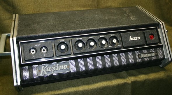
Photo 2 – Kasino Natural bass amplifier came in a heavy duty cabinet
The Kasino Natural bass amp (Photo 2, above) is an early 1970s solid-state amplifier rated at 75 watts RMS (root-mean-square) and 150 watts peak. It has two input jacks for one channel with controls for volume, drive, and three, count’em, three bass controls (Photo 3) – this is our kind of bass amp!
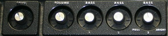
Photo 3 – Kasino Natural tone section included 3 bass tone knobs
Exterior Construction of the Kasino Natural
One of the first things you notice with this amp is that it’s built like a tank! It is very heavy due to its double-cabinet construction:
- Inner Chassis – is a fairly standard sheet metal box enclosure of heavy-duty construction, which slides into the outer chassis.
- Outer Chassis – Made from cast-metal sides (Photo 4) and a Tolex-covered top and bottom.
This design was clearly overkill, as the amplifier industry eventually developed cabinet/chassis designs that weighed less and still offered adequate protection.
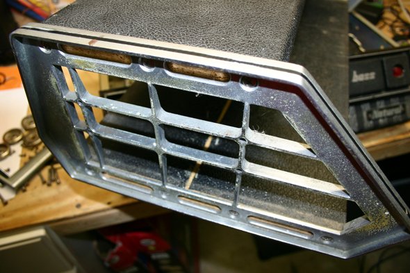
Photo 4 – Kasino Natural outer chassis used a cast-metal frame
Internal Construction of the Kasino Natural
Beyond the cabinet, this amplifier is a fascinating trip into the early history of solid-state guitar amplifier design and construction. It features a hand-drawn printed circuit board (Photo 5) and a variety of metal and plastic transistor types (Photo 6). The construction of this amp is much more suggestive of a custom “one-off” build than of a product manufactured in large numbers.
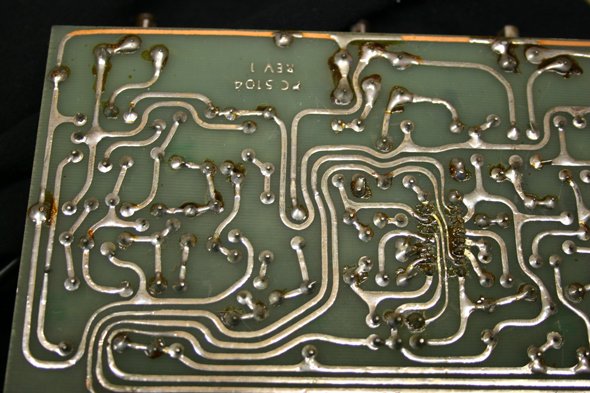
Photo 5 – Kasino Natural printed circuit board was hand-drawn
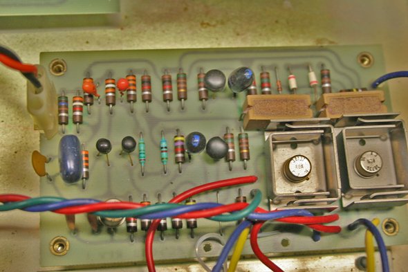
Photo 6 – The 1970s Kasino Natural amp used a variety of transistor types
Initial Inspection
⚠️ SAFETY WARNING: High-Voltage Capacitors Audio amplifiers store dangerous DC voltages in power supply filter capacitors even when disconnected from AC mains power. Always safely discharge power supply capacitors before touching internal components.
Removing the screws to do an internal inspection, we observed the following:
- The amplifier was externally in good condition, but obviously not in its original condition.
- The schematic on the chassis showed a 5104 preamp board and a 5033 power amp board. Kustom/Kasino standardized their circuit boards, and then used them in different combinations in different models.
- The original OEM power cord had been replaced with what appeared to be a long orange extension cord’s plug tail.
- Various internal components showed signs of repair or modification:
- Unused mounting holes in the bottom of the cabinet indicated that there had been prior repairs.
- The filter capacitors had been replaced and the mechanical mountings had been modified.
Initial Power-Up and Test
To do a simple test we connected the amplifier head to a bass speaker cabinet, plugged in a bass guitar, and connected the power cord to the wall socket. We observed the following:
- No sound output
- The front panel lamp was illuminated but its ballast resistor (Photo 7) was running very hot – too hot to touch.
- A critical problem – one of the electrolytic capacitors was outgassing (Photo 8).
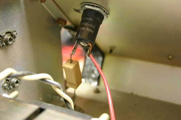
Photo 7 – Interior view showing the illuminated pilot lamp and overheated ballast resistor
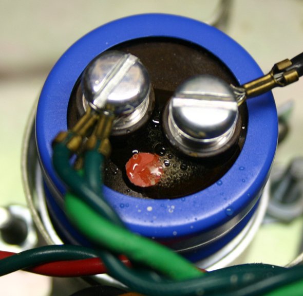
Photo 8 – Electrolytic filter capacitor showing outgassing due to reverse-polarity installation
Outgassing in an electrolytic capacitor generally occurs when the DC voltage is applied in reverse polarity to the capacitor’s terminals, causing a breakdown in the dielectric oxide layer. This in turn causes internal heating and gas buildup. Seeing the capacitor in this condition, we took a quick photo and then turned off the power.
Troubleshooting
So the initial assessment was a bit perplexing. An outgassing capacitor and a ballast resistor running too hot are odd symptoms. After studying the schematic, we could see that the outgassing capacitor had indeed been installed in reverse. This was a bit troubling, as it indicated that the amplifier was not working the last time it was closed up and that someone inexperienced had worked on it.
Bench Equipment
To do audio vintage equipment repair generally only requires basic electronic test gear. For this repair, beyond basic hand tools and connecting cables we used the following:
- Vintage Tektronix oscilloscope
- Fluke digital multimeter (DMM)
- Vintage Elenco audio generator.
Just as importantly, your own five senses play an important role. Up to this point, our senses have taught us a lot by noticing the outgassing capacitor, the unused mounting holes, and the overheating ballast resistor.
Power Supply Troubleshooting
The troubleshooting began with the power supply. Since a replacement capacitor wasn’t immediately available, the one that outgassed was tested to see if it could be temporarily reused. This would only be a temporary solution, as the assumption is that an electrolytic capacitor subjected to reverse-polarity voltage will have been damaged to some extent. The capacitor was tested by first discharging it, then measuring its resistance with a digital multimeter. The characteristic of a good capacitor is that the resistance initially appears as a short circuit (low ohms), then rises to a very high value (open circuit) as the capacitor charges. In this case, the capacitor passed the test, so we decided to use it temporarily to continue troubleshooting.
After reinstalling the capacitor with the correct polarity, we were now measuring ±44 volts from the power supply, which was within the correct range. Reconnecting the speaker and test signal, we found that the amp now “works”, in that an amplified signal comes out of the speaker, though the audio output was not very loud and didn’t sound particularly good.
Signal Tracing
We connected a 400 Hz, 72-millivolt peak-to-peak (mVpp) signal from our audio generator to the amplifier input jack, and began oscilloscope signal tracing. Referring to the schematic in Photo 9, we measured 1000 mVpp at transistor Q3 with the drive and volume at full, indicating that transistors Q1, Q2, and Q3 were amplifying the signal. However,, the 1000 mVpp was reduced to 40 mVpp at the output of IC1a (pin 1), indicating a problem between Q3 and the IC.
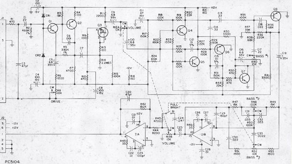
Photo 9 – Factory schematic for the Kustom 5104 Preamp Board used during signal tracing
Testing the DC voltages in the Q4-Q8 tone circuits, we found that the collector voltage on Q4 was only a few tenths of a volt. Likewise, the voltage on the other side of its load resistor R20 was only a few tenths. Since this point connects directly to the +12v supply through R21, a 150-Ω resistor, we realized that something was pulling this line toward ground.
After isolating sections of the circuit by cutting the printed circuit board traces, we found that C2, the 100 µF filter cap, was bad (very low resistance). With C2 removed (one lead lifted from the circuit board), we got good volume and tone, though there was still a bit of low-level noise, scratchiness, and hum. We believed that these symptoms would likely go away once capacitor C2 and the outgassed filter cap were replaced, and the boards were remounted and properly grounded.
Pilot Lamp and Ballast Resistor
With the required capacitors on order, we turned our attention to the front-panel lamp and ballast resistor. This turned out to be a simple problem. The proper bulb for this amp is a #1829 28-volt lamp; however, a #47 6.3-volt lamp was installed. This left a much higher voltage across the ballast resistor, causing it to run very hot. Replacing the bulb fixed the problem.
We ordered a pair of replacement filter capacitors, even though only one was known to be bad. Given the previous repairer’s inexperience, we didn’t know what might have been done to the other filter capacitor, so we decided to replace both. However, these capacitors were too long to mount vertically, so a new clamp was used to mount them horizontally, as shown in Photo 10.
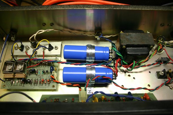
Photo 10 – Replacement filter capacitors mounted horizontally with new chassis clamps
Final Testing and Conclusion
With the new filter capacitors and capacitor C2 installed and all boards mounted, the amp was tested and found to be in perfect working order once again.
By the way, the Vintage Kustom Amp forum was an invaluable resource for fixing this amp. For detailed schematic archives, historical documentation, and community technical support on vintage Kustom and Kasino solid-state electronics, Vintage Kustom serves as a primary reference and repository for restorers and collectors. Check them out at www.vintagekustom.com for literature and information on the vintage Kustom tuck-and-roll amps from the 60’s and 70’s, as well as related products such as guitars and organs. They provide a web board for help with Kustom Gear history, technical information, and repairs, as well as discussions with other collectors. The site also has a classifieds page for buying and selling Kustom gear.
Originally published on GuitarKitBuilder.com

1 thought on “Vintage Kasino Natural Bass Amp Repair: Early 1970s Solid-State Bench Troubleshooting”